Building a CNC Router At Home
What makes up a CNC router?
- Frame (aluminum extrusions)
- Stepper motors
- Lead screws
- Linear rails and bearings
- Bearings (bearing blocks)
- Aluminum plate
- Motor mounts
- Electrical control box with power supply and stepper motor drivers
This design is very rigid and allows the user to machine very accurate parts.
The next couple of pages will explore the parts need to build this type of CNC router.
This CNC router is a simpler version and uses an aluminum frame for the base.

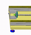
Below is a picture of the X axis. The X axis consists of a pair of linear rails mounted on a pair of aluminum extrusions.
Mounted to the rails are four ball bearing runner blocks . A frame of aluminum extrusions is mounted to the runner blocks and make up the moving table.
In the center is a lead screw with an anti backlash nut, At the far end is a motor mount and a stepper motor. When the stepper motors turns, the table moves back and forth on the linear rails.

A motor mount is attached to the table at the far end. On one end a stepper motor is attached and the opposite end has a bearing block that contains two sets of bearings. The turned end of the lead screw rides on the inside of the bearings.
Not shown is a flexible coupler which is attached to the shaft of the stepper motor and the end of the lead screw.

The other end of the lead screw is attached to another square extrusion with a bearing block. The end of the lead screw is threaded. During assembly, a nut is placed on the thread and tightened (pre loaded) to the point that it remove any play on the lead screw.

Mounted on the lead screw is an anti backlash nut. The nut is attached to the carriage assembly that makes up the moving table assembly.

Below is a picture of the Y axis. The Y axis is constructed similar to the X axis, and is mounted on the back of the Bridge (aluminum extrusion). The Y axis moves back and forth and at the same time moves the Z axis assembly.

The Z axis assembly consists of a pair of rails and four bearings. Attached to the bearings is a flat plate. Between the rails is a lead screw and anti backlash nut.
One end of the lead screw is attached to the shaft on the stepper motor through a flexible coupler.
The front plate moves up and down powered by the stepper motor.
Attached to the front plate is another plate that has a router bracket attached.


0 Comments:
Post a Comment
Subscribe to Post Comments [Atom]
<< Home